

Which Mode Enables You To View And Change The Configuration Of A Cisco Router?

![]()
![]()
![]()
A big number of commands are available on Cisco routers, equally well equally many different protocols and features that tin can exist used to institute a network. Navigating through Cisco IOS® Software tin be confusing and intimidating for someone new to Cisco routers. This section will familiarize you lot with some of the bones router commands that are commonly used, as well equally some typical router management tasks in the included labs.
![]()
![]()
The following commands are used to gather information on a Cisco IOS Software-based router when attempting to larn basic information well-nigh a router, or maybe troubleshooting protocol-contained bug:
- evidence version
- evidence running-config
- show interfaces
- show logging
- show tech-support
Let'south examine these commands further to run into how they can be used to obtain valuable information.
![]() bear witness version
bear witness version
You will use the show version command in the simulation environment. This command displays the configuration of the organization hardware, the software version, and the names and sources of configuration files and the boot images. This control too displays information about how the system was terminal started and how long the router has been running since that first. Sample output from the evidence version control follows:
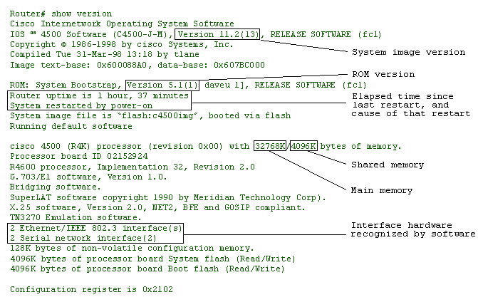
This information indicates the running version of the Cisco IOS Software. This software has many different versions of the Cisco IOS Software, each of which supports a variety of features. The version of Cisco IOS Software on the router plays a major office in dictating the capabilities and services of the router.
Router Uptime and System Restart
The router uptime tin be checked to brand sure the router has been in continuous operation since it was last restarted. If the uptime is inconsistent with the terminal known router maintenance, the router may have restarted because of problems with the electrical circuit it is connected to, or because of bug with the router itself. The "System restarted by" line displays a log of how the arrangement was concluding booted, whether by normal system startup or because of a system error. The following display is an example of a organization error that is generally the result of an effort by the router to access a nonexistent accost:
Organisation restarted by bus mistake at PC 0xC4CA, accost 0x210C0C0
Interface Hardware Inventory
The interface hardware inventory should include all interface processors installed in the router. If any interfaces that are installed in the router do not evidence up in the inventory, at that place may exist hardware problems with the interface processor itself, or the router may exist running a version of the Cisco IOS Software that does non support that interface type.
Shared Memory
This is the memory the interface processors apply for buffering packets. Every bit the name suggests, all the interface processors in a router share this memory, and performance issues can effect if there is not enough. Information technology may be necessary to upgrade the retentiveness if such an issue occurs.
Main Memory
This retentivity is used to shop the running configuration and all routing tables. In extremely large networks, it is possible for the routing tables to go then large they exceed the main retention chapters. When this happens, the router volition crash. It may be necessary to upgrade the memory if such an effect occurs.
![]() show running-config
show running-config
All the commands that are entered on a router are stored in the current running configuration that is maintained in RAM. This command tin can be very useful when gathering bones information or troubleshooting because information technology allows the user to verify the commands that have been administered on the router. You will use the evidence running-config command in the simulation labs.
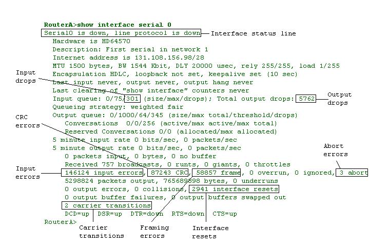
You volition use the show interfaces command in the do labs. This command displays statistics for the network interfaces. Sample output from the show interfaces command is shown beneath. Considering your display volition depend on the type and number of interface cards in your router, merely a portion of the display is shown, in this case for a serial interface.
![]() Click on the Netbit icon to the right to view an animation nigh Cyclic Redundancy Check (CRC).
Click on the Netbit icon to the right to view an animation nigh Cyclic Redundancy Check (CRC).
![]()
Interface and Line Protocol Status
The interface and line protocol condition output gives information related to the concrete country of the interface (the commencement role of the output) and shows the state of messages at the data link level (the second part of the output, following the comma).
When an interface is operating and communicating correctly, at that place is only i possible condition output:
- Serial x is upwards, line protocol is upwards
Remember that this output is meant to correspond to the serial interface output shown to a higher place. If an Ethernet interface were being examined, the output would plain change accordingly to "Ethernet x is up, line protocol is upwardly."
You can identify five possible problem states in the interface condition line of the show interfaces serial brandish:
- Serial ten is down, line protocol is down
- This state indicates a cable or interface problem. The remote end may exist administratively shut down, a state of affairs that could cause both ends to go downwardly. To bring an interface up, utilize the no form of the shutdown control under the interface configuration mode.
- Serial x is upwardly, line protocol is downwardly
- This state is ofttimes attributed to a clocking or framing problem. Check to brand sure that clocking has been set on the correct end, keepalives are being sent correctly, and the encapsulation type on both ends match.
- Serial x is upward, line protocol is upwards (looped)
- This state indicates that a loop exists in the circuit. This trouble could be associated with an existing loopback interface.
- Series x is up, line protocol is downwardly (disabled)
- This state often indicates a hardware problem and may be associated with a phone visitor service trouble.
- Serial x is administratively down, line protocol is downwardly
- This state indicates that the shutdown command has been administered on the interface. To bring the interface up, utilise the no shutdown command under interface configuration style.
Output Drops
Output drops announced in the output of the evidence interfaces serial control when the system is attempting to hand off a package to a transmit buffer only no buffers are available.
![]() Output drops are acceptable nether sure conditions. For instance, if a link is known to be overused (with no way to remedy the situation), it is often considered preferable to drop packets rather than holding them, particularly for protocols that back up flow control and can retransmit data, such every bit TCP/IP.
Output drops are acceptable nether sure conditions. For instance, if a link is known to be overused (with no way to remedy the situation), it is often considered preferable to drop packets rather than holding them, particularly for protocols that back up flow control and can retransmit data, such every bit TCP/IP.
![]() Click on the Netbit icon to the right to view an blitheness about buffering.
Click on the Netbit icon to the right to view an blitheness about buffering.
![]()
Input Drops
Input drops appear in the output of the testify interfaces serial EXEC control when too many packets from that interface are withal existence candy in the organization.
Input Errors
If input errors appear in the show interfaces serial output, they have several possible sources. The most likely sources are related to physical layer issues, including bad hardware, a noisy line, a bad connection, or incorrect equipment. Other potential causes include noisy lines and wrong data conversion.
![]() Whatever input error value for cyclic redundancy check (CRC) errors, framing errors, or aborts above one pct of the total interface traffic suggests some kind of link problem that should be isolated and repaired.
Whatever input error value for cyclic redundancy check (CRC) errors, framing errors, or aborts above one pct of the total interface traffic suggests some kind of link problem that should be isolated and repaired.
Interface Resets
Interface resets that announced in the output of the show interfaces serial EXEC command are the result of missed keepalive packets. Interface resets may occur considering of issues such as congestion on the line, a bad line, or faulty equipment.
Carrier Transitions
Carrier transitions announced in the output of the testify interfaces series EXEC command whenever at that place is an break in the carrier signal (such as an interface reset at the remote finish of a link). Carrier transitions may exist caused by physical changes to the line (cablevision unplugged or damaged) or by faulty equipment.
![]() evidence logging
evidence logging
This control displays the state of syslog fault and event logging, including host addresses, and whether console logging is enabled. This command also displays Uncomplicated Network Management Protocol (SNMP) configuration parameters and protocol activity.
Router# show logging Syslog logging: enabled Console logging: disabled Monitor logging: level debugging, 266 messages logged. Trap logging: level informational, 266 messages logged. Logging to 192.180.2.238 SNMP logging: disabled, retransmission after 30 seconds 0 messages logged
The following tabular array describes meaning fields shown in the command brandish.
| Field | Description |
| Syslog Logging | When enabled, system logging messages are sent to a UNIX host that acts as a syslog server; that is, it captures and saves the messages. |
| Console Logging | If enabled, this field states the level; otherwise, it displays disabled. |
| Monitor Logging | This shows the minimum level of severity required for a log message to be sent to a monitor concluding (not the console). |
| Trap Logging | This field gives the minimum level of severity required for a log message to be sent to a syslog server. |
| SNMP Logging | This field shows whether SNMP logging is enabled and the number of letters logged, and the retransmission interval. |
![]() show tech-support
show tech-support
Utilise this control to aid collect general information about the router when you are reporting a problem to the Cisco Technical Assist Center (TAC). This control displays the equivalent of the following show commands:
- show version
- show running-config
- show controllers
- prove stacks
- testify interfaces
- evidence buffers
- show processes memory
- show processes cpu
The output of about of these commands is of use only to your technical support representative.
![]()
![]()
Although most configurations on a Cisco Router volition probably occur when a network is initially being prepare up or an upgrade or enhancement is being performed, you lot may see some basic maintenance tasks during routine interaction with a router. A listing of some of the mutual router management tasks are below. The simulation labs that follow will reinforce your understanding of these tasks past walking you lot through each of these procedures.
- Providing a router hostname
- Setting up passwords
- Disabling DNS lookup
- Setting up logging
- Setting timestamps for logging and debugging
- Defining console, auxiliary, and virtual last settings
- Setting up a Comm Server to access your routers more easily
- Handling password recovery
- Downloading a software epitome from a TFTP server
- File direction tasks
- Cisco Discovery Protocol
![]()
![]()
For security purposes, passwords are often configured on Cisco routers to restrict access. This password tin can be forgotten or lost and it may need to be recovered to gain access to the router. The process for recovering a lost password varies from platform to platform, because in that location are many different types of Cisco products. Several password recovery techniques for different Cisco products can be constitute on Cisco.com by searching on the words "password recovery."
Though the actual password-recovery processes for unlike routers may vary, each process follows the following basic steps:
- Configure the router to boot upwards without reading the configuration memory (nonvolatile RAM, or NVRAM). This is sometimes called the "test system fashion."
- Reboot the organisation.
- Access enable mode (this can exist done without a password if you lot are in examination organization mode).
- View or change the countersign, or erase the configuration.
- Reconfigure the router to boot up and read the NVRAM as it normally does.
- Reboot the system.
![]() Some countersign recovery requires a terminal to issue a Interruption indicate; yous must be familiar with how your concluding or PC terminal emulator issues this signal. Several break sequences for different platforms and setups are provided on Cisco.com by searching on the words "break sequence."
Some countersign recovery requires a terminal to issue a Interruption indicate; yous must be familiar with how your concluding or PC terminal emulator issues this signal. Several break sequences for different platforms and setups are provided on Cisco.com by searching on the words "break sequence."
![]() To view a NetBit on how to complete password recovery on a Cisco 2600 Router, click on the NetBit icon to the correct.
To view a NetBit on how to complete password recovery on a Cisco 2600 Router, click on the NetBit icon to the correct.
![]()
The Cisco Discovery Protocol (formerly known as CDP) is a proprietary, media- and protocol-independent protocol that runs on all Cisco manufactured equipment, including routers, bridges, access servers, and switches. With Cisco Discovery Protocol, network direction applications tin can acquire the device blazon and the Simple Network Management Protocol (SNMP) agent address of neighboring devices. This enables applications to ship SNMP queries to neighboring devices.
Cisco Discovery Protocol essentially allows administrators to gain basic information nearly all other devices attached to a Cisco device. The type of information that can be obtained using Cisco Discovery Protocol includes the hostname, platform (blazon of device), and capabilities of fastened devices. Cisco Discovery Protocol can also be used to obtain the network accost of the interface of an attached device.
Cisco Discovery Protocol runs on all media that back up Subnetwork Access Protocol (SNAP), LAN, Frame Relay, and ATM media. Cisco Discovery Protocol runs over the data link layer merely. Therefore, two systems that support dissimilar network-layer protocols tin larn about each other.
Each device configured for Cisco Discovery Protocol sends periodic messages to a multicast address. Each device advertises at least one accost at which it tin can receive SNMP messages. The advertisements besides contain time-to-live, or holdtime, information, which indicates the length of time a receiving device should agree Cisco Discovery Protocol information before discarding it.
The section that follows outlines some of the basic Cisco IOS® commands related to Cisco Discovery Protocol. A lab is provided, after in this module, to give you some experience configuring and using Cisco Discovery Protocol in a network environment.
![]() Basic Cisco IOS Commands Related to Cisco Discovery Protocol
Basic Cisco IOS Commands Related to Cisco Discovery Protocol
To set the frequency of Cisco Discovery Protocol transmissions and the agree time for Cisco Discovery Protocol packets, perform the following tasks in global configuration mode:
| Chore | Control |
| Specify frequency of transmission of Cisco Discovery Protocol updates. | cdp timer seconds |
| Specify the amount of time a receiving device should agree the information sent by your device before discarding it. | cdp holdtime seconds |
Cisco Discovery Protocol is enabled by default. To disable Cisco Discovery Protocol and later on reenable information technology, perform the following tasks in global configuration mode:
| Task | Command |
| Disable Cisco Discovery Protocol. | no cdp run |
| Enable Cisco Discovery Protocol. | cdp run |
Cisco Discovery Protocol is enabled by default on the router and is as well enabled past default on all supported interfaces to send and receive Cisco Discovery Protocol information. To disable and later reenable Cisco Discovery Protocol on an interface, perform the following tasks in interface configuration mode:
| Job | Command |
| Disable Cisco Discovery Protocol on an interface. | no cdp enable |
| Enable Cisco Discovery Protocol on an interface. | cdp enable |
![]()
![]()
Now that you have explored some of the commands related to basic router settings and gathered data, let's look at the show version of some routers to obtain more data about them. Continue with Lab: Router Basics.

Source: https://www.cisco.com/E-Learning/bulk/public/tac/cim/cib/using_cisco_ios_software/07_basic_commands_tasks.htm
Posted by: pratherfiefultoothe.blogspot.com
0 Response to "Which Mode Enables You To View And Change The Configuration Of A Cisco Router?"
Post a Comment